Phase shifter circuit EN/ES
Operational amplifiers have proven to have a huge range of usefulness in various types of applications, just change some combination of passive or active components to give great utilities.
So far we have only tried to present circuits with a single amplifier because these are easier to understand for a general audience, however when two or more amplifiers are combined in a circuit the potential usefulness of them increases as well as the quality of the results.
Following the thread of simple applications will be presented in this article a phase shifter circuit using only one operational amplifier.
Los amplificadores operacionales han demostrado tener un enorme rango de utilidad en diversos tipos de aplicaciones, solo basta con cambiar alguna combinación de componentes pasivos o activos para darle grandes utilidades.
Hasta ahora solo se ha intentado presentar circuitos con un solo amplificador porque estos son más fáciles de comprender para un público general, sin embargo cuando se combinan dos o más amplificadores en un circuito el potencial de utilidad de los mismos aumenta al igual que la calidad de los resultados.
Siguiendo el hilo de aplicaciones sencillas se presentará en este artículo un circuito desfasador usando solo una amplificador operacional.

We must remember that one of the characteristics of alternating current is the phase angle which determines the magnitude for an alternating voltage at a given instant of time.
Two voltages are said to be out of phase when they have the same voltage, frequency and waveform values but their magnitudes are different at any given instant of time (as shown in the first image).
This feature becomes relevant at a special level when dealing with systems that work with more than one source of alternating voltage such as three-phase motors, load transfer systems among others that include signal conditioning.
Consider the following circuit:
Debemos recordar que una de las características de la corriente alterna es el ángulo de fase el cual determina la magnitud para un voltaje alterno en un instante de tiempo determinado.
Se dice que dos voltajes están desfasados cuando estos tienen los mismos valores de voltaje, frecuencia y forma de onda pero sus magnitudes son distintas en cualquier instante de tiempo determinado (tal como se muestra en la primera imagen.)
Esta característica se vuelve relevante en un nivel especial cuando se trata de sistemas que trabajan con más de una fuente de voltaje alterno como motores trifásicos, sistemas de transferencia de cargas entre otros que incluyen el acondicionamiento de señales.
Consideremos el siguiente circuito:

At first glance we may think that this is a variable filter by the combination between the potentiometer and the capacitor on the non-inverting input, however when we see the inverting input it has characteristics of an inverting amplifier, but then we look at the input signal to discover that it reaches both terminals simultaneously.
That is precisely the magic of electronics, just change a couple of little things and we have an application completely different from any other, in this case it is a phase shifter.
The explanation of operation is very simple, in the non-inverting input we must make the input resistance and the feedback resistance have the same value so that the gain is 1, remember that this circuit should only modify the phase and not other characteristics such as frequency and amplitude.
The non-inverting input circuit is responsible for adjusting the amount of phase shift that the signal will suffer, the combination wRC will present a delay at the output compared to the input (where w is the pulsed frequency which in Hz is 2pif) and it is this delay that creates the phase shift, the potentiometer allows to adjust the desired phase shift value that can be calculated with the following formula:
A simple vista podemos pensar que se trata de un filtro variable por la combinación entre el potenciómetro y el capacitor en la entrada no inversora, sin embargo cuando vemos la entrada inversora tiene características de un amplificador inversor, pero luego miramos la señal de entrada para descubrir que llega a ambos terminales de forma simultánea.
Esa es precisamente la magia de la electrónica, solo basta cambiar un par de cositas y tenemos una aplicación completamente distinta a cualquier otra, en este caso se trata de un cambiador de fase.
La explicación de operación es muy sencilla, en la entrada no inversora debemos hacer que la resistencia de entrada y la de realimentación tengan el mismo valor para que la ganancia sea 1, recordemos que este circuito solo debe modificar la fase y no otras características como frecuencia y amplitud.
El circuito en la entrada no inversora es el que se encarga de ajustar la cantidad de desfase que sufrirá la señal, la combinación wRC presentara un retardo a la salida frente a la entrada (siendo w la frecuencia pulsátil que en Hz es 2pif) y es este retardo el que crea dicho desfase, el potenciómetro permite ajustar el valor de desfase deseado que se puede calcular con la fórmula siguiente:

If we know what angle we want and we just want to know at what value we must place the potentiometer to obtain that angle we just need to clear Ri from the formula since Ri represents the potentiometer, so we can use the following formula for the calculation.
Si sabemos qué ángulo deseamos y solo queremos conocer a que valor debemos colocar el potenciómetro para obtener dicho angulo solo debemos despejar Ri de la formula ya que Ri representa el potenciometro, asi podemos usar la siguiente formula para el cálculo.

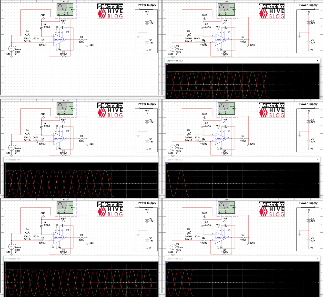
To check the operation of the circuit we add an oscilloscope that allows us to visualize the input and output.
Para comprobar el funcionamiento del circuito añadimos un osciloscopio que nos permita visualizar la entrada y la salida.

Now that all is said and done, let's move on to the simulation to check the behavior of the circuit.
Ya que todo está dicho pasemos a la simulación para comprobar el comportamiento del circuito.

In this way we add to our collection another circuit with operational amplifiers, simple, easy and economical but very useful 😉.
De esta forma añadimos a nuestra colección otro circuito con amplificadores operacionales, simple, facil y economico pero muy útil. 😉

¡Enhorabuena!
✅ Has hecho un buen trabajo, por lo cual tu publicación ha sido valorada y ha recibido el apoyo de parte de CHESS BROTHERS ♔ 💪
♟ Te invitamos a usar nuestra etiqueta #chessbrothers y a que aprendas más sobre nosotros.
♟♟ También puedes contactarnos en nuestro servidor de Discord y promocionar allí tus publicaciones.
♟♟♟ Considera unirte a nuestro trail de curación para que trabajemos en equipo y recibas recompensas automáticamente.
♞♟ Echa un vistazo a nuestra cuenta @chessbrotherspro para que te informes sobre el proceso de curación llevado a diario por nuestro equipo.
🏅 Si quieres obtener ganancias con tu delegacion de HP y apoyar a nuestro proyecto, te invitamos a unirte al plan Master Investor. Aquí puedes aprender cómo hacerlo.
Cordialmente
El equipo de CHESS BROTHERS